|
|
|
||||
|
|
|
|
|
|
|
|
|
|
|
|
|
|
|
 |
|
ExampleLaser exposure objective |
||||
|
Computer-generated holograms are deployed nowadays to test lenses, in the production or beamforming of lasers, in correcting objectives and in many other applications. To produce the fine structures, a laser beam focused on light-sensitive material (photoresist) inscribes a high-resolution pattern.
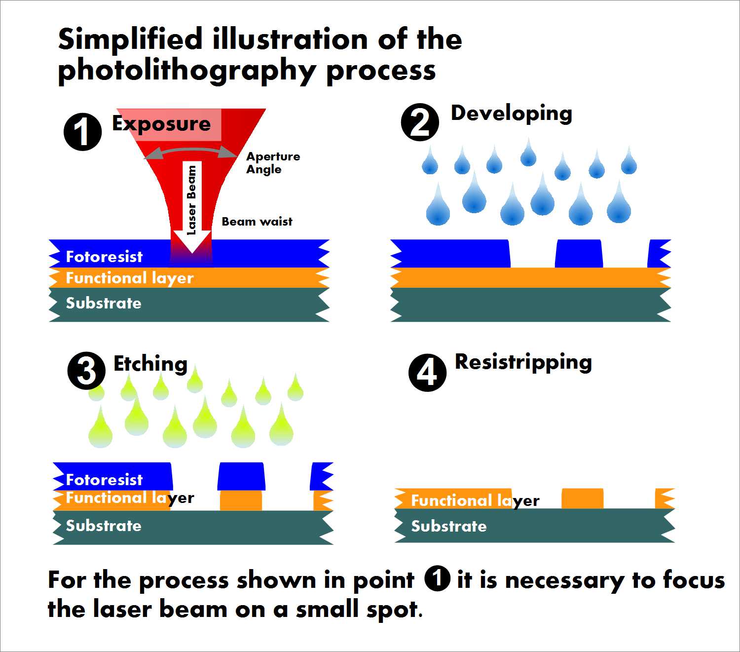
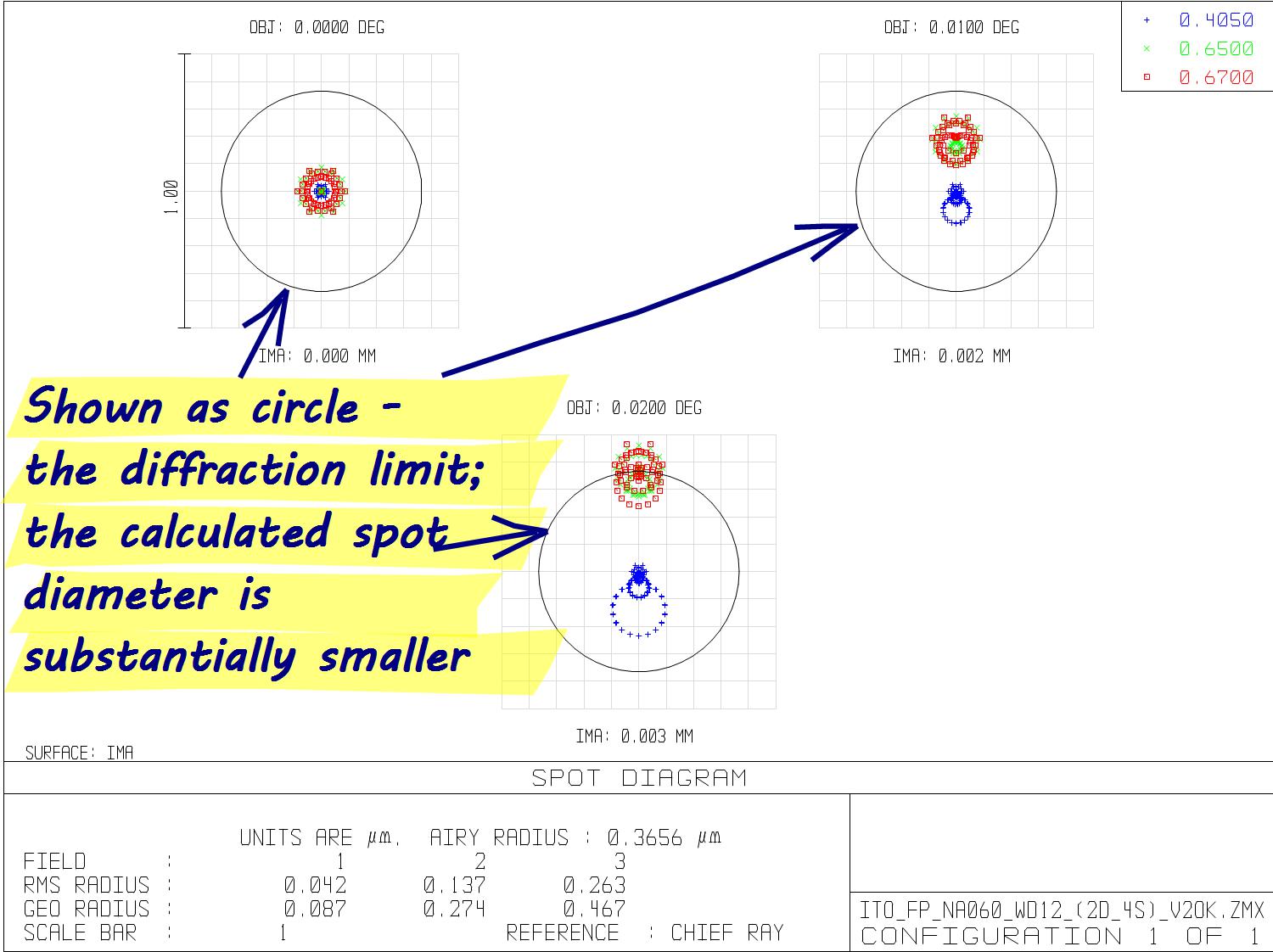
Left: Illumination and photolithography process to create fine structures Right: Spot diagram of the three calculated illumination objectives
Demands are high on the objectives that focus these lasers—for one thing, the beam’s energy most be focused on the smallest possible point; and for another, the focusing of the autofocus beam must also be extraordinarily good. The mass of the objective is limited for the autofocus mechanism to function optimally. 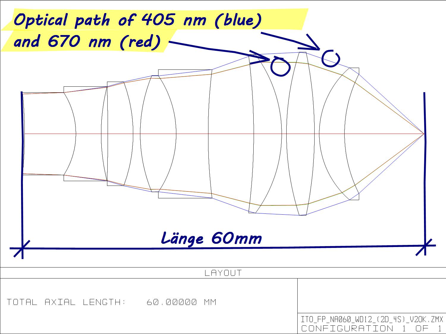
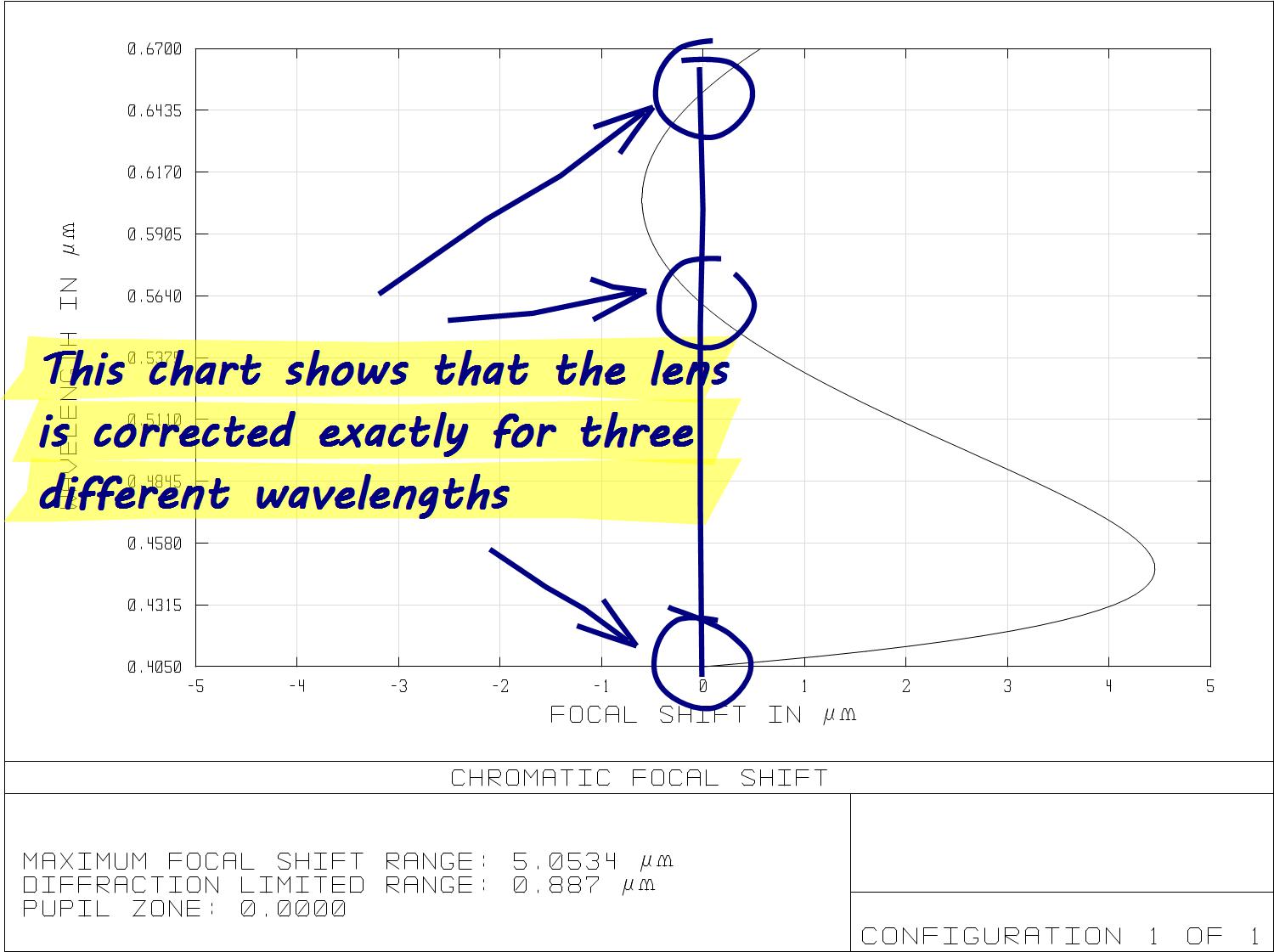
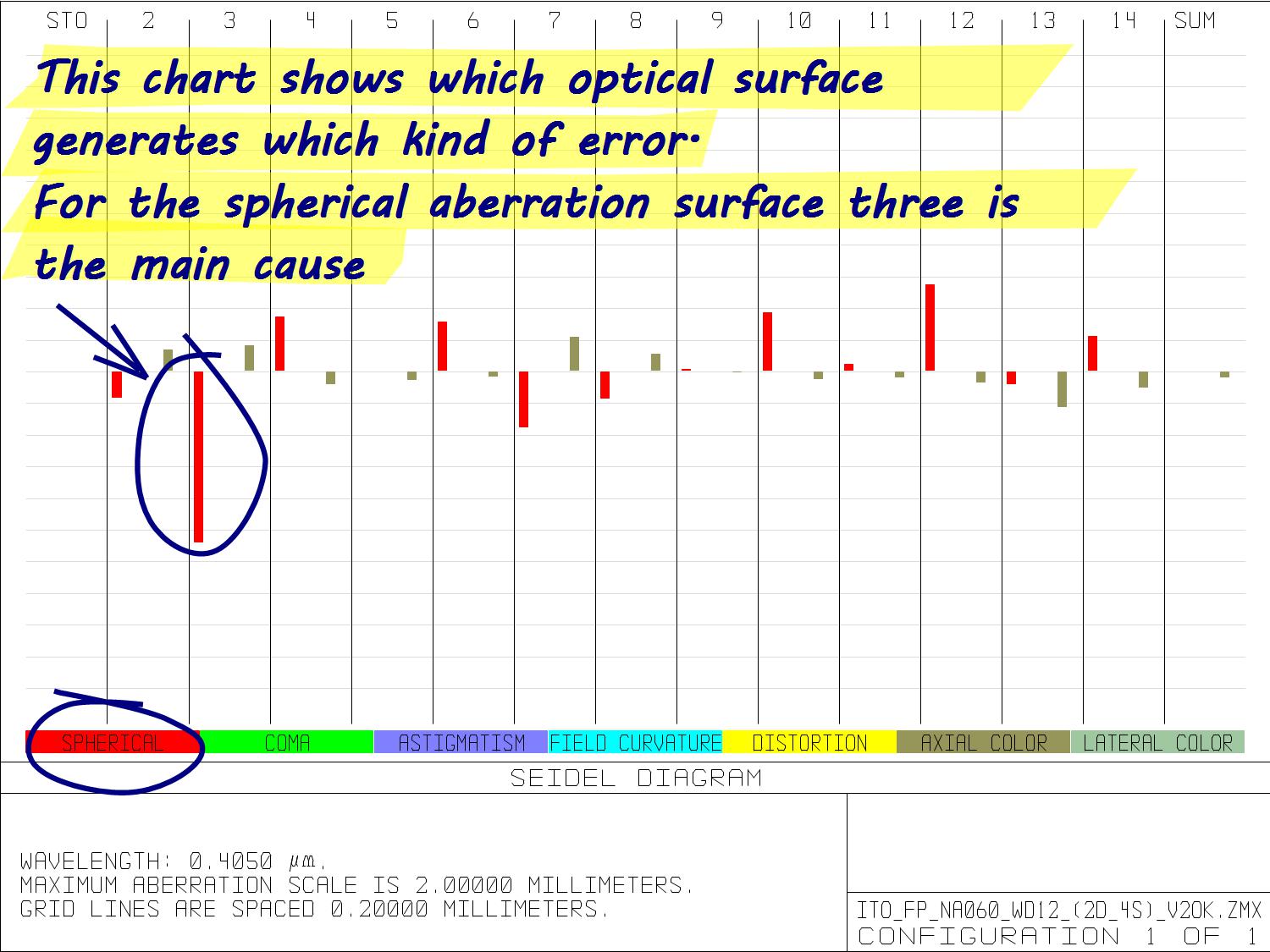
Left: Beampath of one of the calculated objectives Center: The chromatic focal shift diagram shows the focal deviation by wavelength Right: The Seidel diagram shows which surfaces lead to which kinds of imaging errors
|
To achieve the result, we calculated three objectives for two different imagers. Here we outline the process of creating one of these objectives:
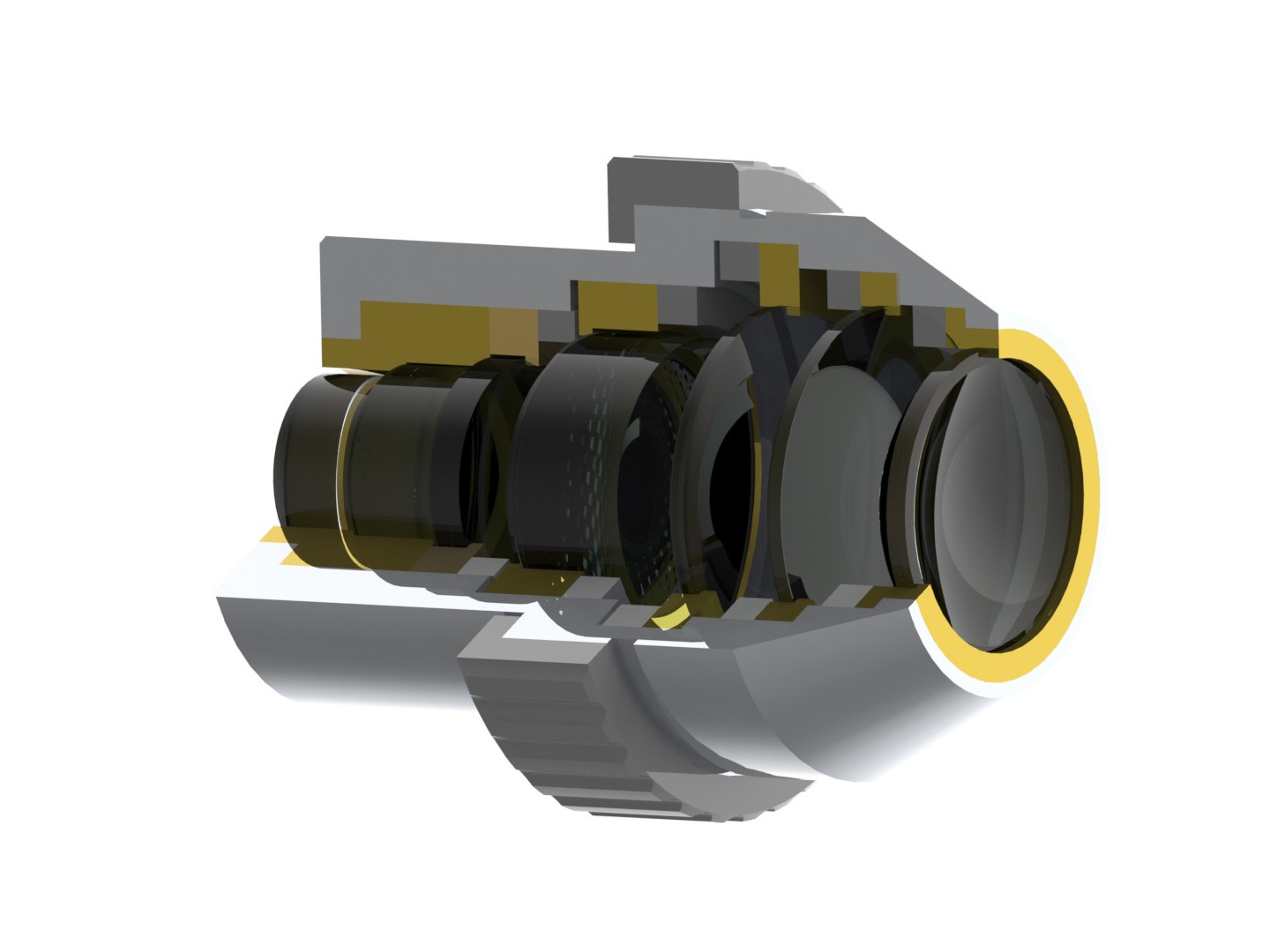
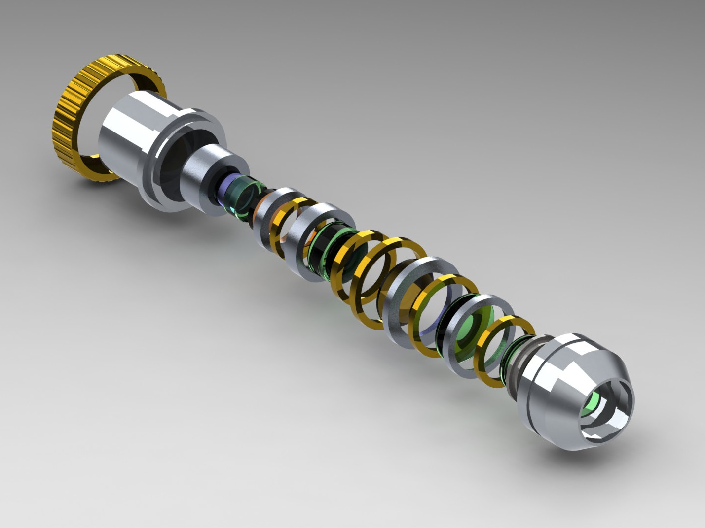
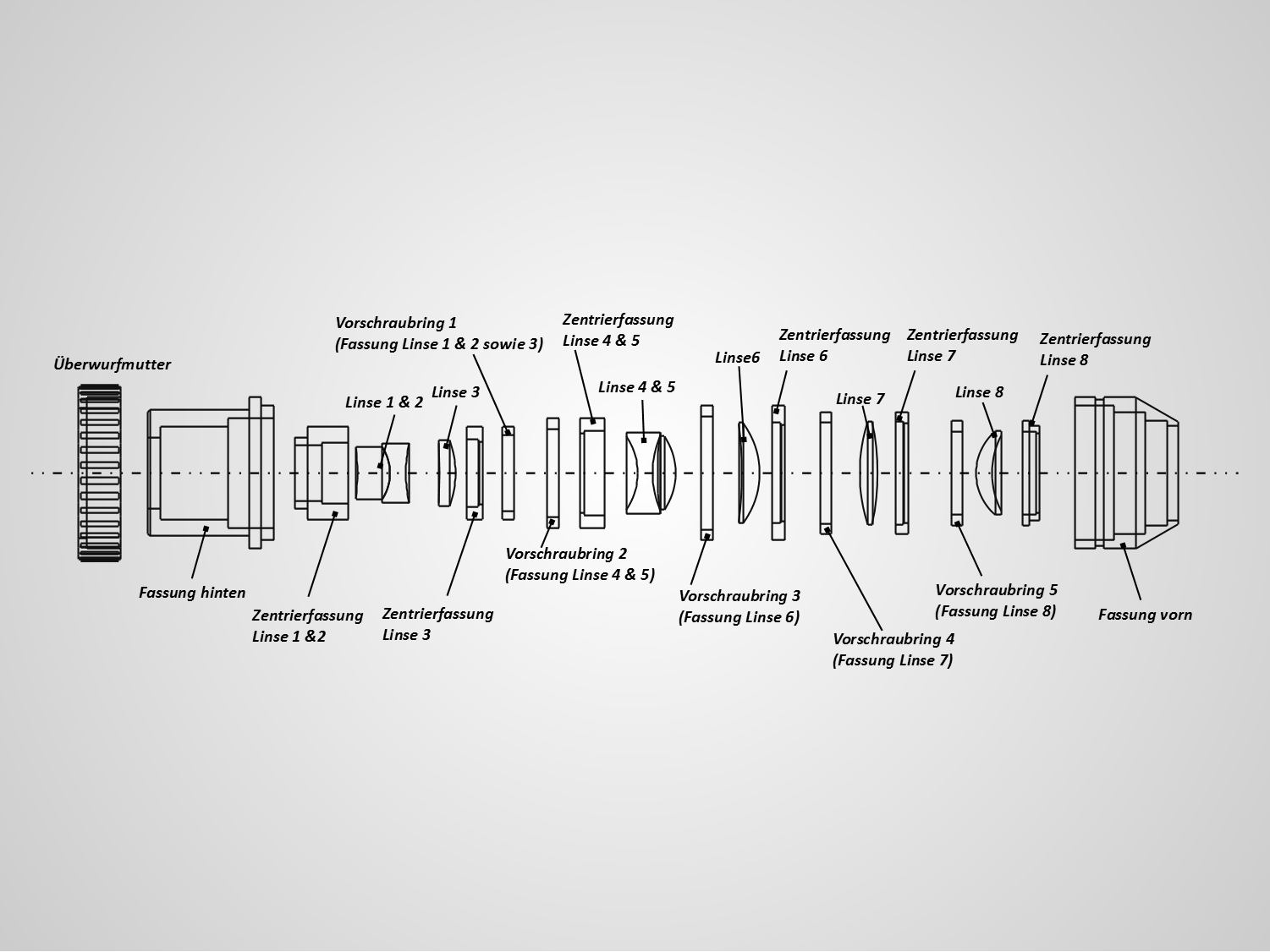
Left: Cross section of the objective Center: Exploded representation of the same objective Right: Representation of the concept for the housing and centering adjustment |
|||
|
|
Contact |
 |
News |
 |
|
Terms of Service | |||||||